ASUS ASUSPRO P2540FB-DM0038R RAM upgrade specifications

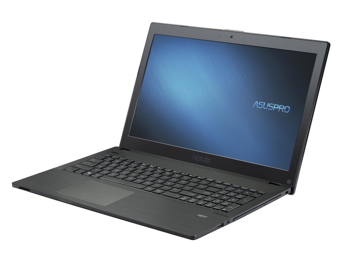
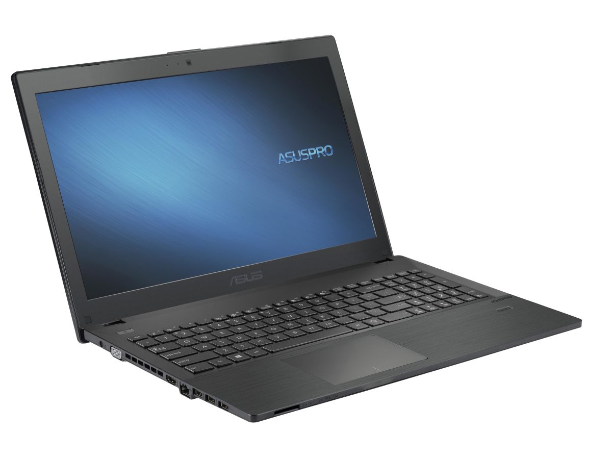


The ASUS ASUSPRO P series P2540FB-DM0038R laptop features DDR4-SDRAM memory with one SO-DIMM slot for upgrade capacity. The system contains on-board memory combined with one expandable SO-DIMM slot, supporting maximum RAM specifications of 20 GB total. Memory upgrade compatibility requires DDR4-SDRAM modules operating at 2400 MHz frequency. The single SO-DIMM slot accommodates additional memory installation for enhanced multitasking performance and application handling capabilities.
Memory Upgrade Specifications
| Specification | Value |
|---|---|
| Memory slots | 1x SO-DIMM |
| Form factor | On-board + SO-DIMM |
| Memory type | DDR4-SDRAM |
| Frequency | 2400 MHz |
| Maximum RAM | 20 GB |
| Voltage | 1.2V |
| Number of pins | 260-pin |
| Interface | PC4 |
| PC Speed Rating | PC4-2400 (PC4-19200) |
| Bandwidth | 19.2 GB/s |
| Laptop Release date | 01 March 2019 |
Additional Notes
- The ASUS ASUSPRO P2540FB-DM0038R features soldered memory alongside a single SO-DIMM slot, limiting future expansion to one physical module addition.
- The 20 GB maximum capacity indicates 4 GB of non-removable soldered RAM paired with a 16 GB SO-DIMM module as the highest achievable configuration.
- Users currently below maximum capacity can only upgrade by replacing the existing SO-DIMM module, as no second slot exists for additional memory installation.
- The 2400 MHz specification requires matching frequency modules to maintain dual-channel operation with the onboard memory, as mixed speeds will downclock to the lowest common frequency.
- Dual-channel bandwidth benefits depend on installing a SO-DIMM module, as the soldered memory alone operates in single-channel mode with reduced data throughput.
- The asymmetric memory configuration creates flex mode dual-channel operation where only matched capacity portions run in dual-channel, while excess capacity operates in single-channel mode.
- Standard DDR4 SO-DIMM voltage of 1.2V must be maintained, as low-voltage or overclocked modules may cause system instability or boot failures with the fixed onboard component.
- Physical access to the single SO-DIMM slot typically requires bottom panel removal, which may involve warranty seal breakage depending on regional service policies.
- CAS latency timing compatibility between aftermarket SO-DIMM modules and the soldered memory impacts overall system latency, though JEDEC standard timings ensure basic functionality.
- The permanent 4 GB soldered component prevents complete memory replacement in case of failure, leaving only the SO-DIMM slot as the serviceable upgrade path.