ASUS TUF Dash FX516PM-HN026 RAM upgrade specifications

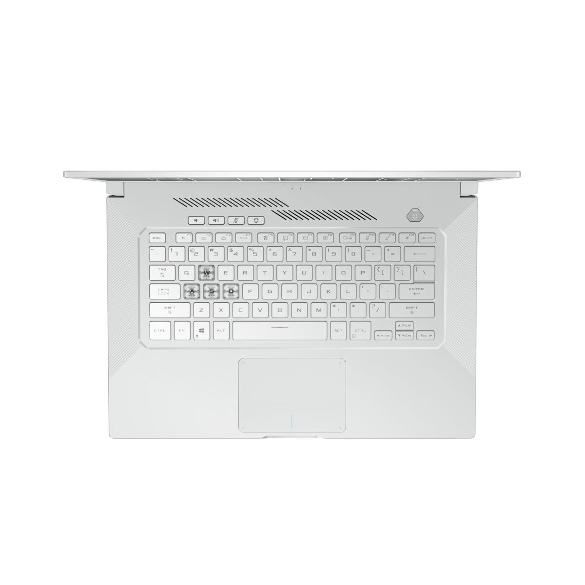
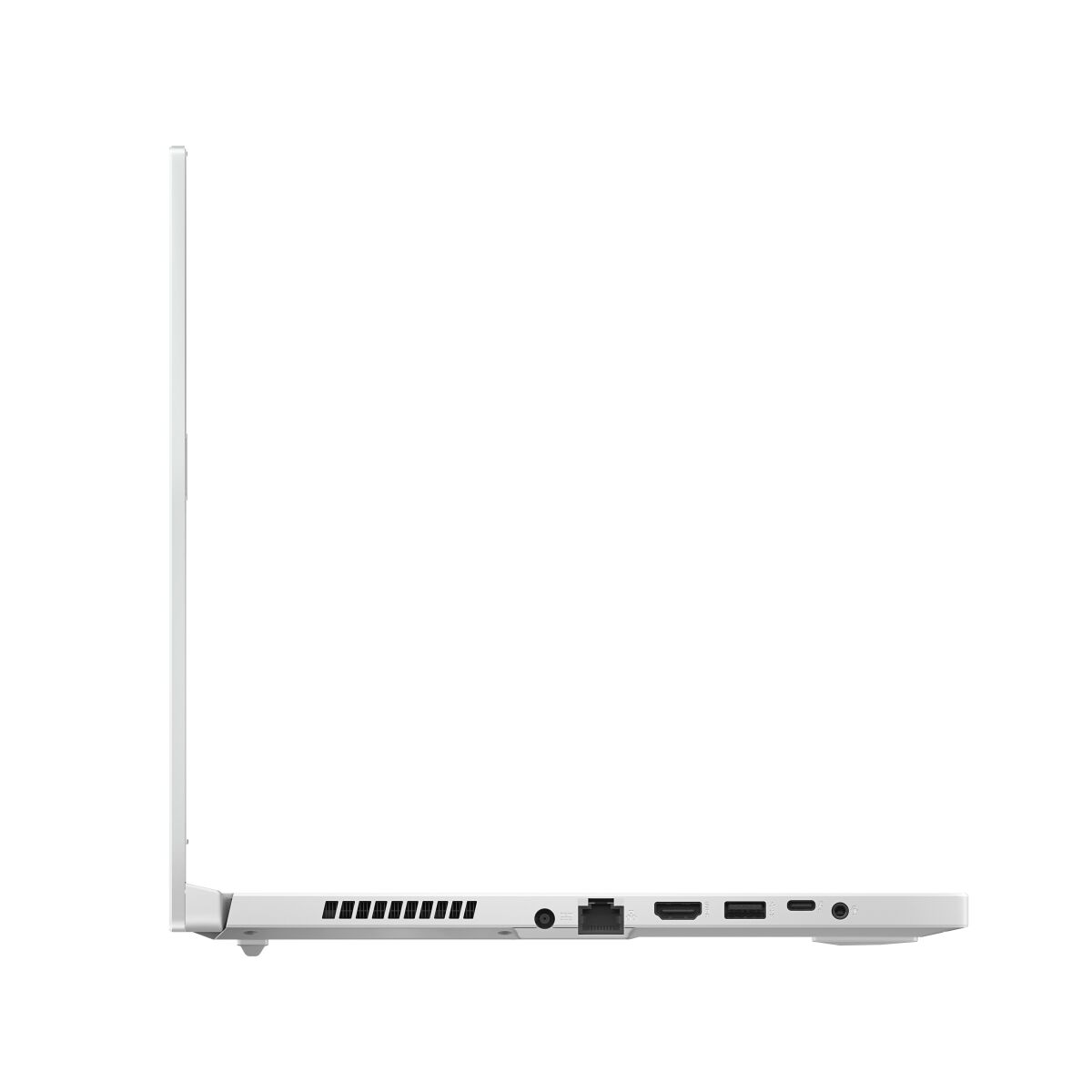
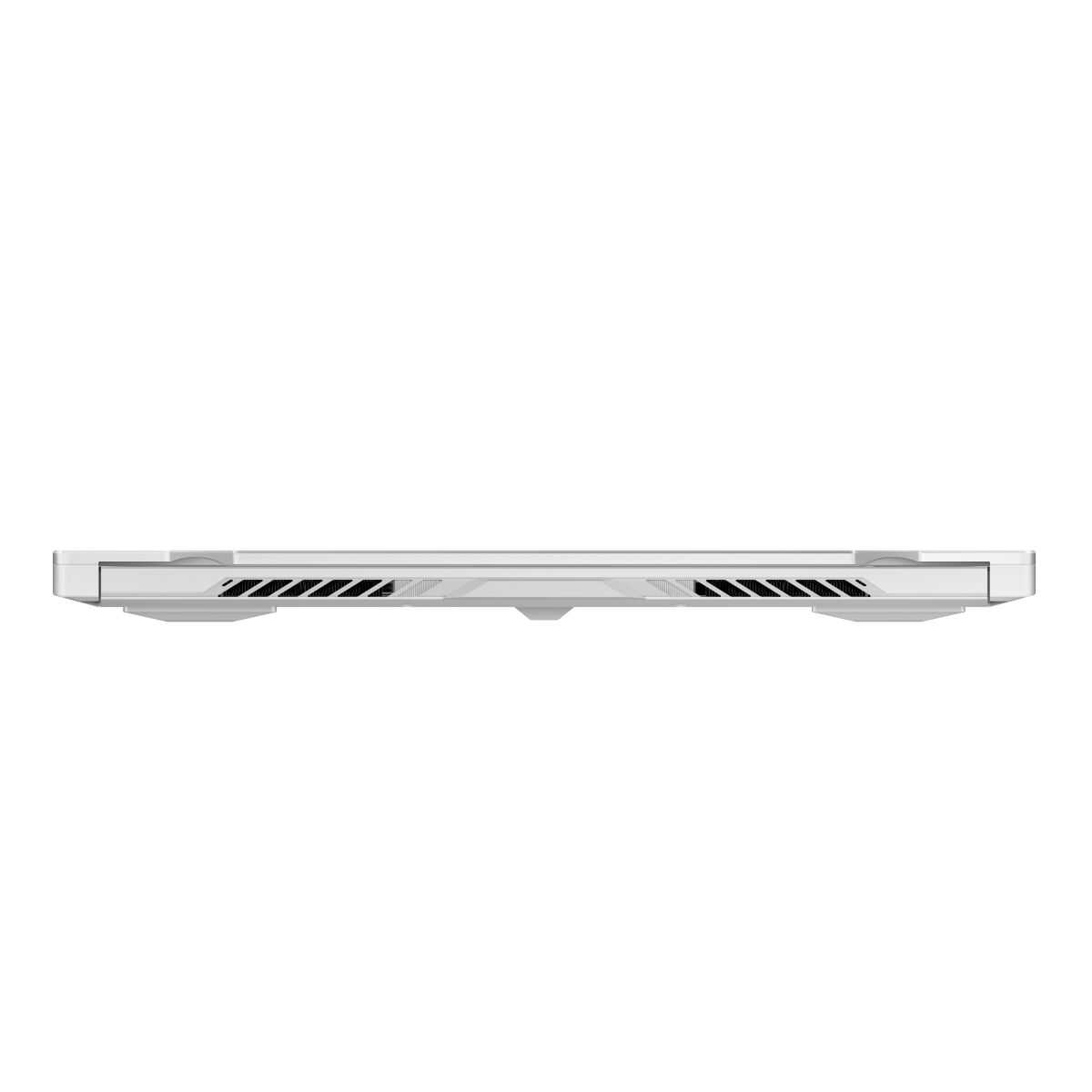
The ASUS TUF Dash F15 FX516PM-HN026 features DDR4-SDRAM memory with one SO-DIMM upgrade slot available. The laptop contains 3200 MHz DDR4 memory modules, supporting maximum RAM capacity of 32 GB through the removable SO-DIMM slot. Compatible upgrade specifications for the FX516PM-HN026 accommodate DDR4-SDRAM modules, allowing users to expand memory capacity by replacing the existing module in the single SO-DIMM slot to reach the maximum 32 GB specifications for this TUF Dash series model.
Memory Upgrade Specifications
| Specification | Value |
|---|---|
| Memory slots | 1x SO-DIMM |
| Form factor | On-board + SO-DIMM |
| Memory type | DDR4-SDRAM |
| Frequency | 3200 MHz |
| Maximum RAM | 32 GB |
| Voltage | 1.2V |
| Number of pins | 260-pin |
| Interface | PC4 |
| PC Speed Rating | PC4-3200 (PC4-25600) |
| Bandwidth | 25.6 GB/s |
| Laptop Release date | 25 January 2021 |
Additional Notes
- The presence of on board memory indicates that a portion of the system RAM is permanently soldered to the motherboard and cannot be replaced or removed.
- Upgrading the **ASUS TUF Dash FX516PM-HN026** to the maximum supported 32 GB requires the installation of a single 16 GB or 24 GB module into the solitary expansion slot depending on the base factory configuration.
- Dual channel memory performance is only active for the capacity where the on board chip and the SO-DIMM module match in size.
- Capacity utilized beyond the matching on board amount will operate in single channel mode which creates a memory bandwidth bottleneck for data intensive applications.
- The system is limited to DDR4 architecture which prevents the installation of newer DDR5 modules due to physical pin layout and voltage differences.
- Installing a module with a frequency higher than 3200 MHz results in the hardware automatically downclocking the RAM to match the speed of the integrated memory controller.
- Physical access for hardware internal modification requires the removal of the bottom chassis panel which exposes sensitive components to electrostatic discharge risks.
- Latencies are determined by the slowest chip present meaning a high performance lower CAS latency module will sync to the timings of the soldered memory.